Computer-controlled cutting
So it's the 4th week since I begin my fab journey. In this week, I got following assignments,
I have learn and used two machines in the lab. Vinyl cutter and Laser cutter. So let's see what they do...
Vinyl cutter
A vinyl cutter is a type of computer-controlled machine. Small vinyl cutters look like a desktop printer. Like a printer controls a nozzle, the computer controls the movement of a sharp blade over the surface of the material. This blade is used to cut out shapes and letters from sheets of thin self-adhesive plastic (vinyl). The vinyl can then be stuck to a variety of surfaces depending on the adhesive and type of material.
The one major limitation with vinyl cutters is that they can only cut shapes from solid colours of vinyl. A design with multiple colours must have each colour cut separately and then layered on top of each other as it is applied to the substrate. Also, since the shapes are cut out of solid colours, photographs and gradients cannot be reproduced with a stand alone cutter.
In our fab lab, we use Roland Camm-1 vinyl cutter.
Machine details and operation
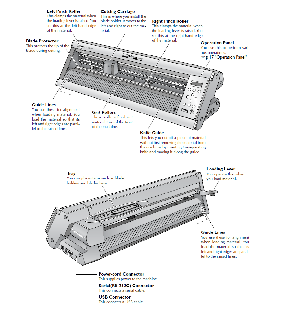
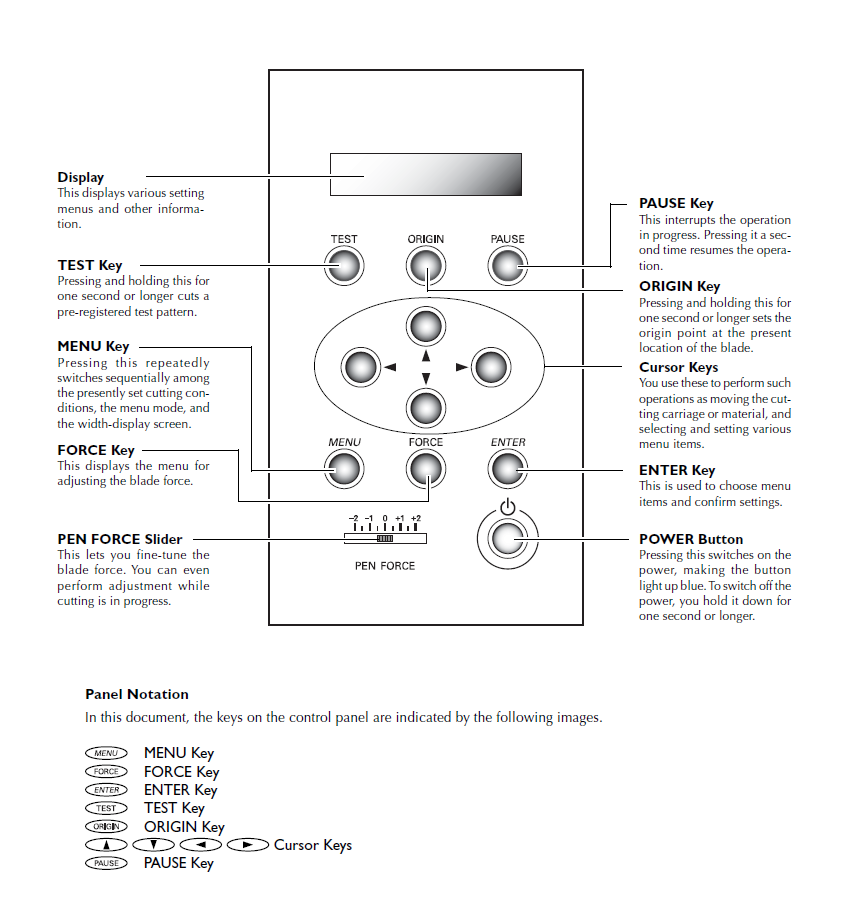
Our instructors showed us how to operate the vinyl cutter. Here is the user manual for the above machine
So I have to make a design for cutting out from the vinyl cutter. I designed a logo in week 3 in inkscape. But vinyl cutter only recognize black colour. So I need to make the image black amd white. For that I took it's bitmap using "trace bitmap" option.
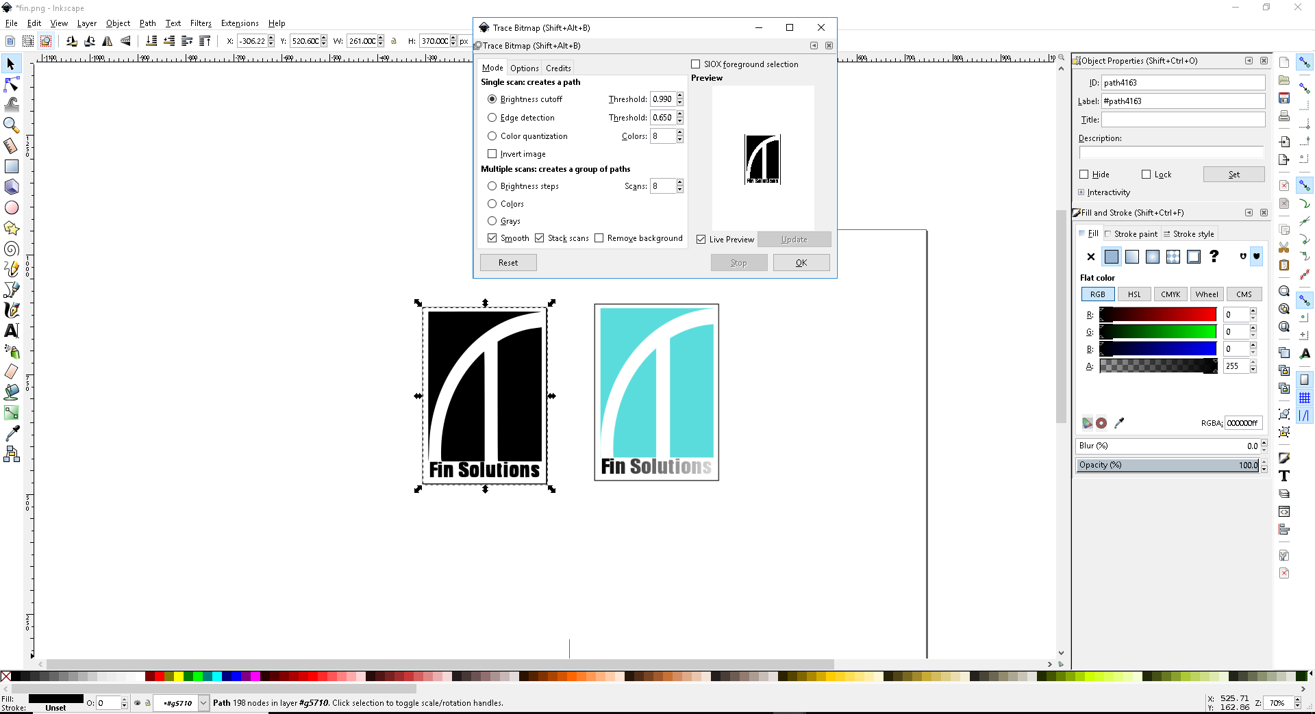
Then I exported the same image as a png image and opened fab tools for vinyl cutter. The following window shows up on the screen
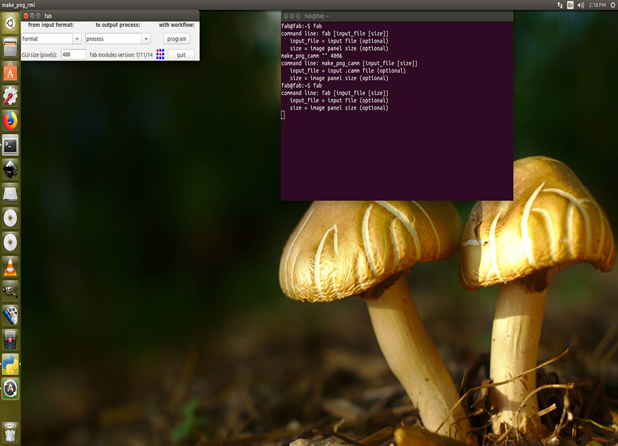
Now set the image format as png and machine as roland vinyl cutter (camm) and enter make camm.Now control window will pop up
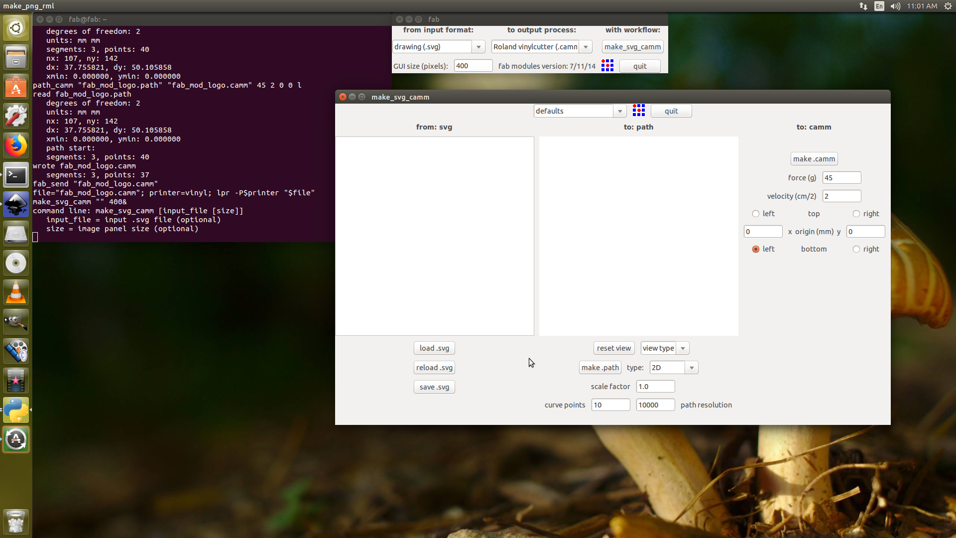
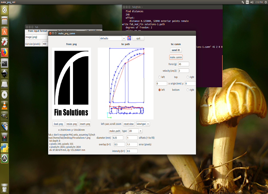
I load the image to the window and press . then I make it camm. Now I need to set the machine for printing..
Settings up Vinyl cutter
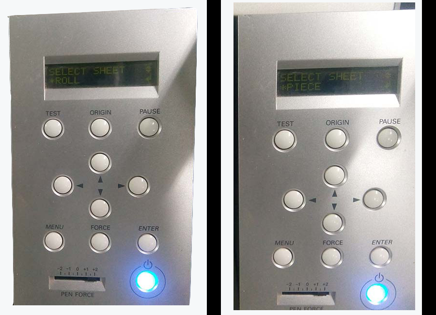
For setting up the vinyl cutting first switch it on. Now insert the vinyl sheet by pulling the "loading lever". Select between "Roll and piece" and push enter.
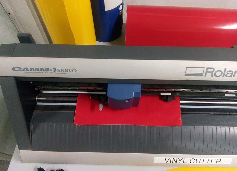
Now adjust the correct force and push send it in the window in the computer. It will start cutting the layout. After removing the unwanted areas, cover the cut area using a masking tape
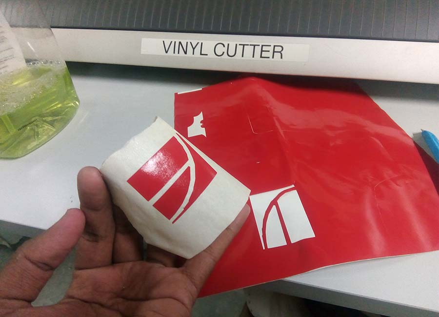
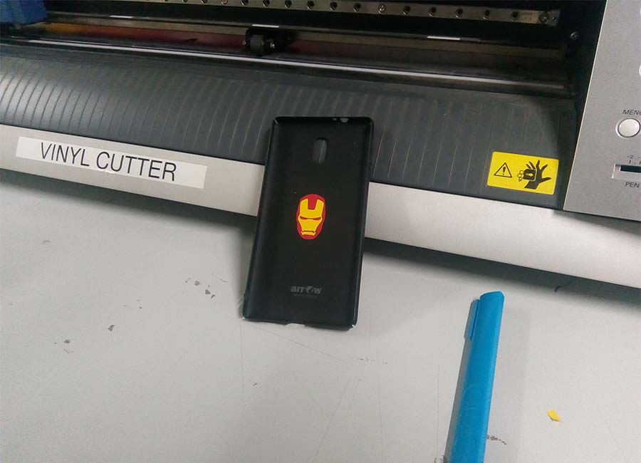
Now you can place it on your phone or laptop...
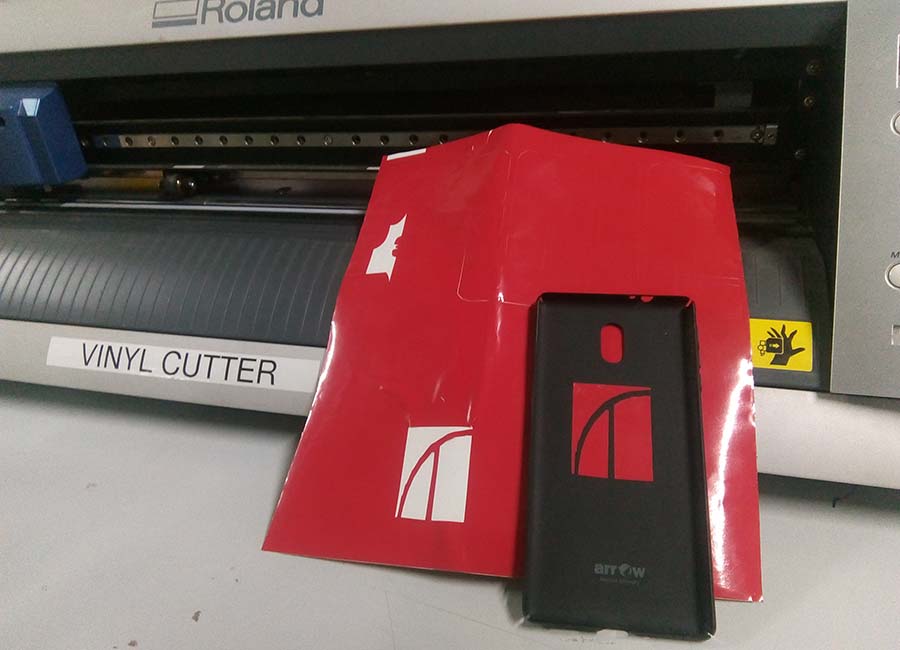
I have also tried out some other combinations. You can download them here...
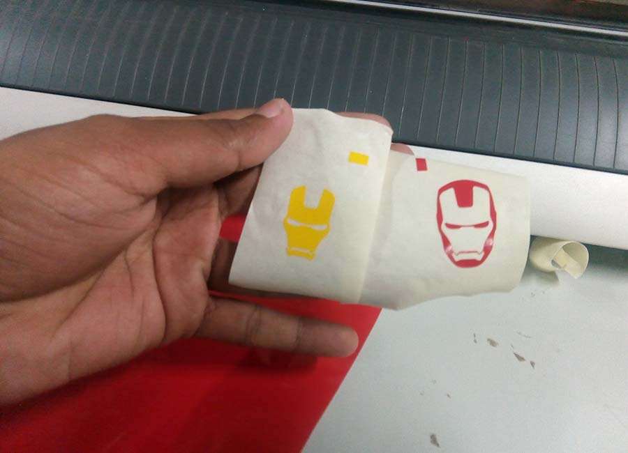
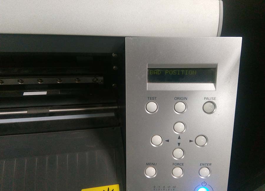
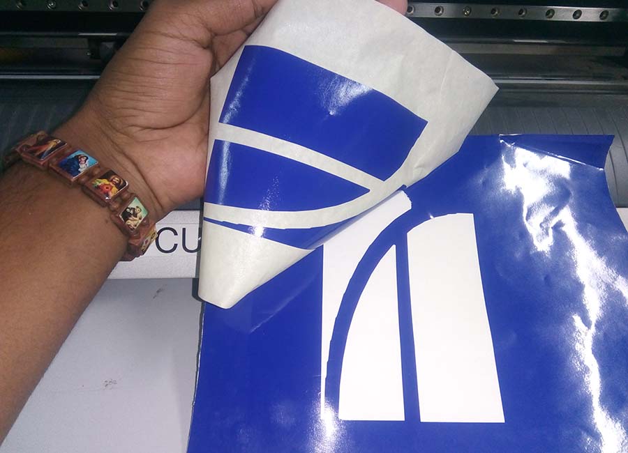
I didn't got perfect in the first try. There were some misfits in the design. First one was bad position of the sheet during loading. It is solved by reinstalling the sheet. Another thing was during separation from the main sheet with masking tape. It tear apart ...
So that's it for vinyl cutter, Now we can start with laser cutters ...
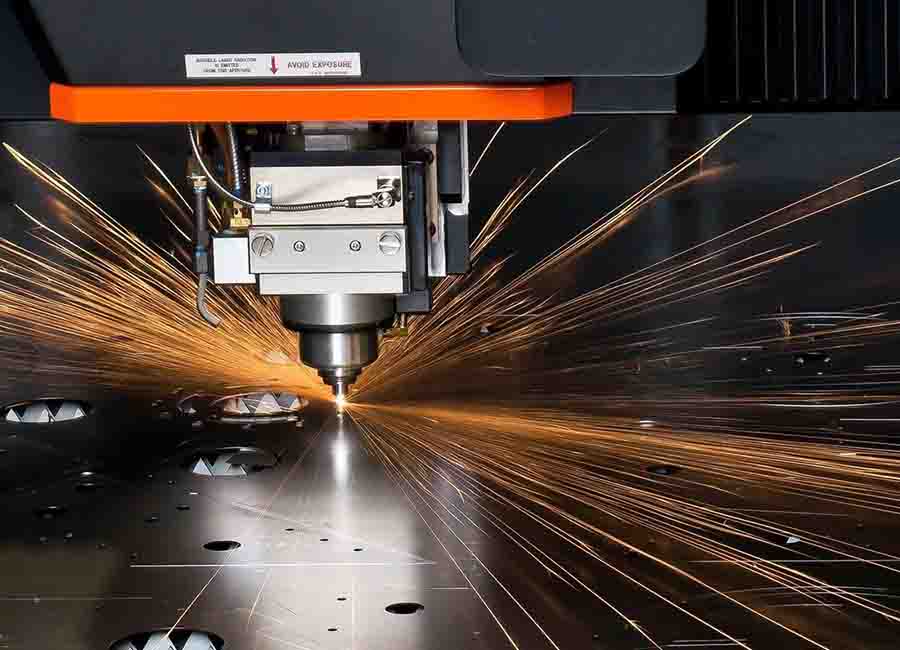
Laser cutter
Laser cutting is a technology that uses a laser to cut materials, and is typically used for industrial manufacturing applications, but is also starting to be used by schools, small businesses, and hobbyists. Laser cutting works by directing the output of a high-power laser most commonly through optics. The laser optics and CNC (computer numerical control) are used to direct the material or the laser beam generated. A typical commercial laser for cutting materials involved a motion control system to follow a CNC or G-code of the pattern to be cut onto the material. The focused laser beam is directed at the material, which then either melts, burns, vaporizes away, or is blown away by a jet of gas,[1] leaving an edge with a high-quality surface finish. Industrial laser cutters are used to cut flat-sheet material as well as structural and piping materials.
Machine details
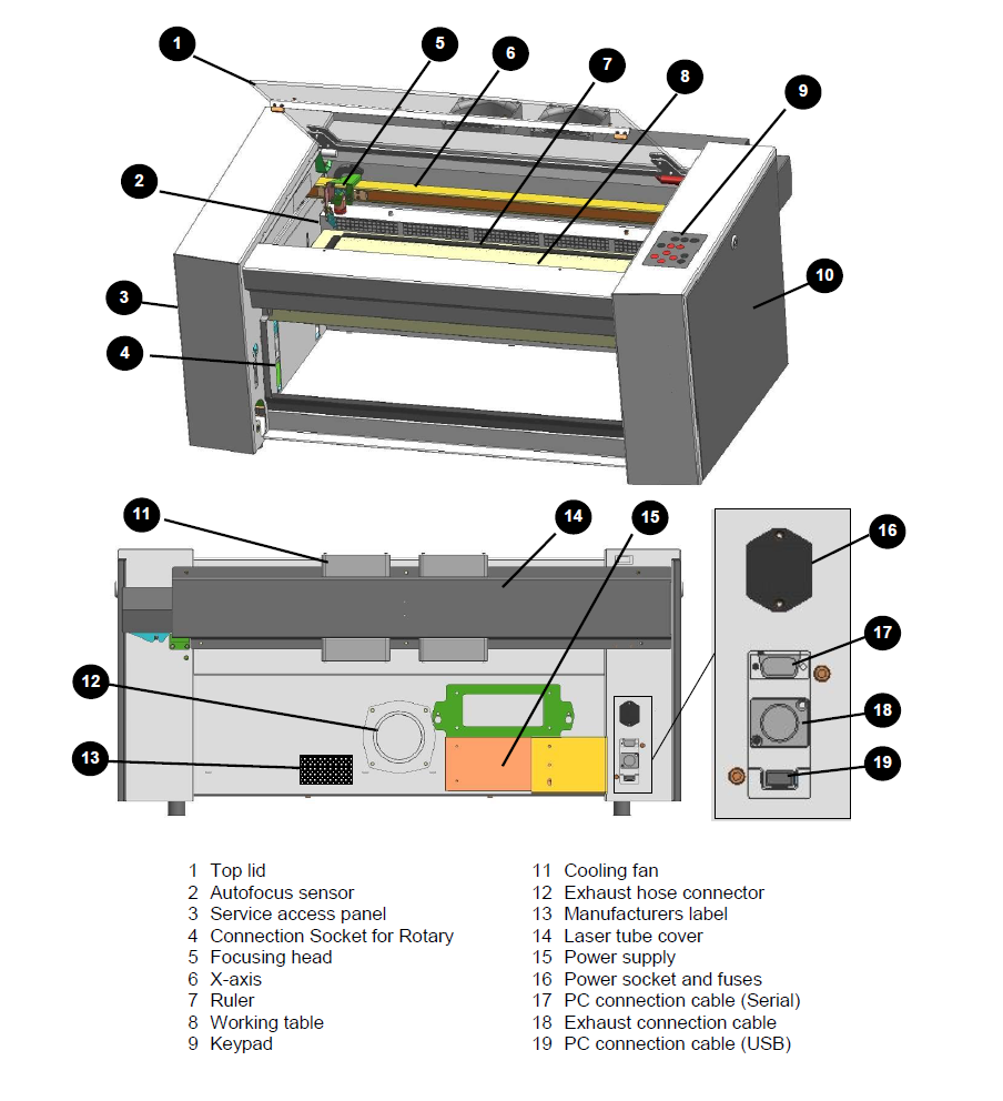
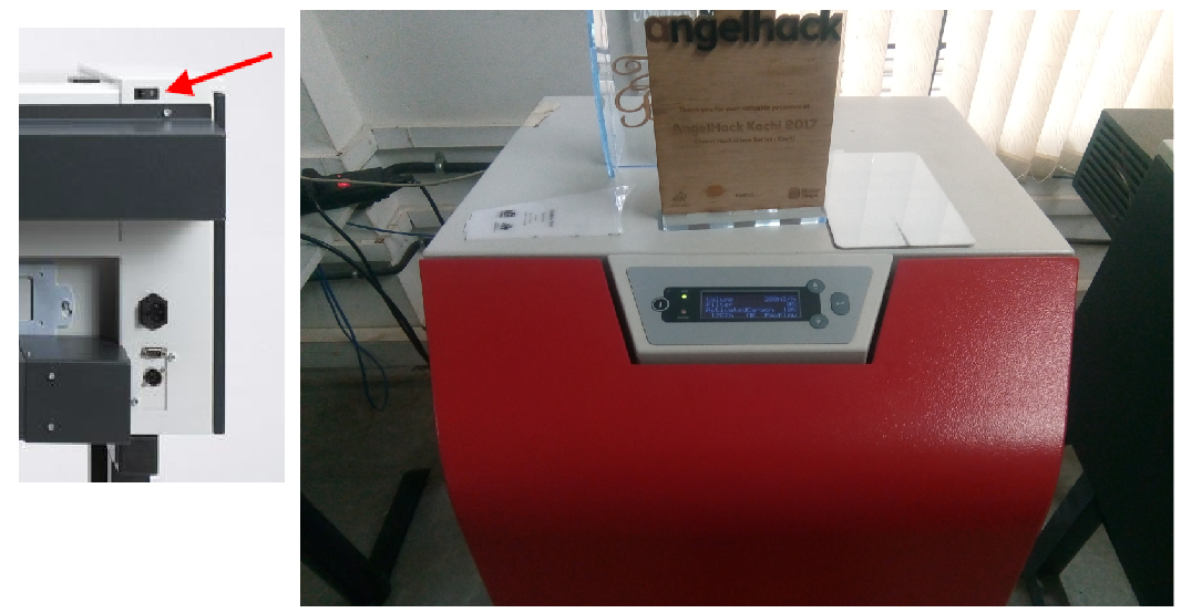
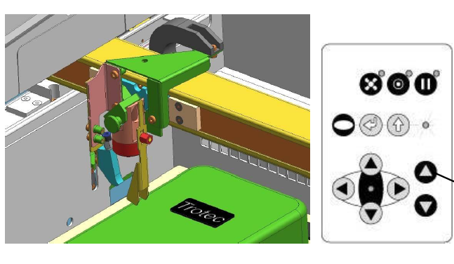
Move the processing head over the material to be engraved by means of the positioning keys X/Y.Hang the focus tool on the external ring of the working head so that the focus tool can move unhindered. Move the working table upwards by pressing the Z positioning key . While doing this carefully observe the focus tool.Before the focus tool reaches the work piece, move the working table upwards only very slowly and step by step by briefly tapping the positioning key, until the tool tilts to the side. Now the lens is focused onto the surface of the material (Source: Users maual.)
Here is the video of setting the X&Y axes..
Here is the video of setting Z axis..
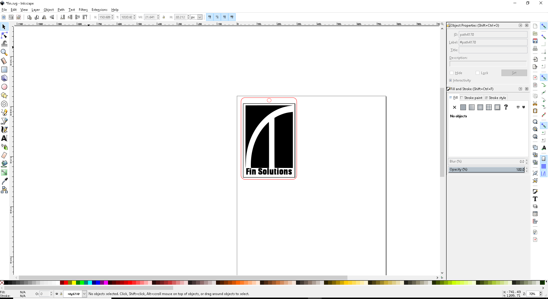
Now the machine is ready to do any work. I want to take a test drive with my previously designed logo. So I have need to cut it into a key chain. For that I load the image into inkscape and took it's bitmap. For cutting into a key chain, I drew a rectangle around it and colour it outline as red. Now add a circle for the hole and press print..
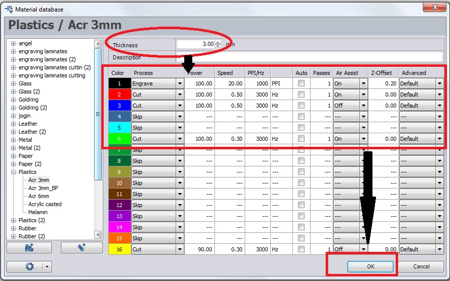
When print option is given, Trotec laser driver software comes online. First I set red to cut and black to engrave. Then I selected material and thickness.
Below I have marked the parts of with Trotec laser software UI's parts
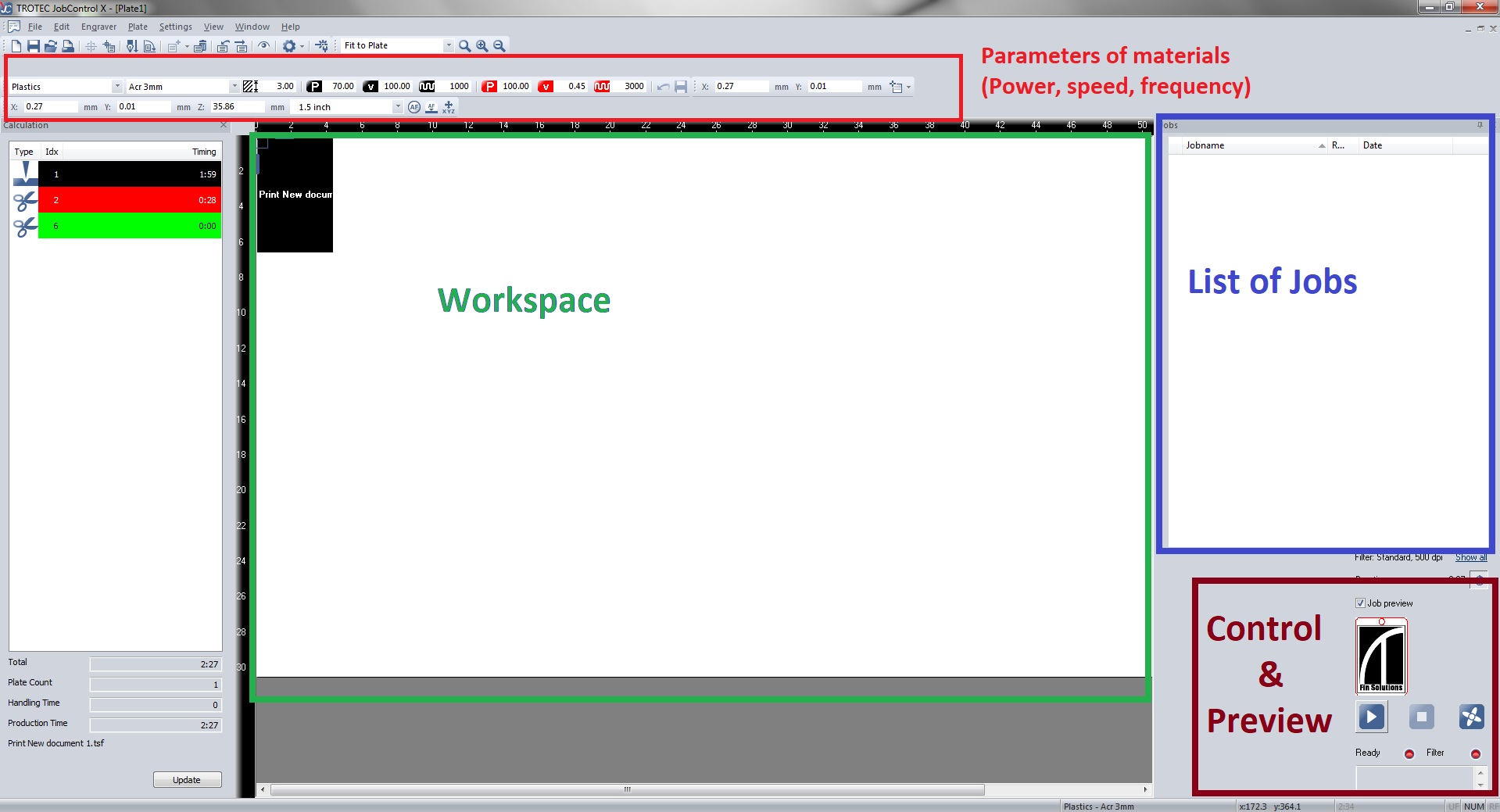
The colour of the design parts determines the process. But we need to do it first. For that double click the work space. You will get the window below. Set engraving colour as Black and cuting colour as Red . Also check the speed, Velocity and power. Ensure the air assist is on. Otherwise the toxic gas will remain on the laser engraver.
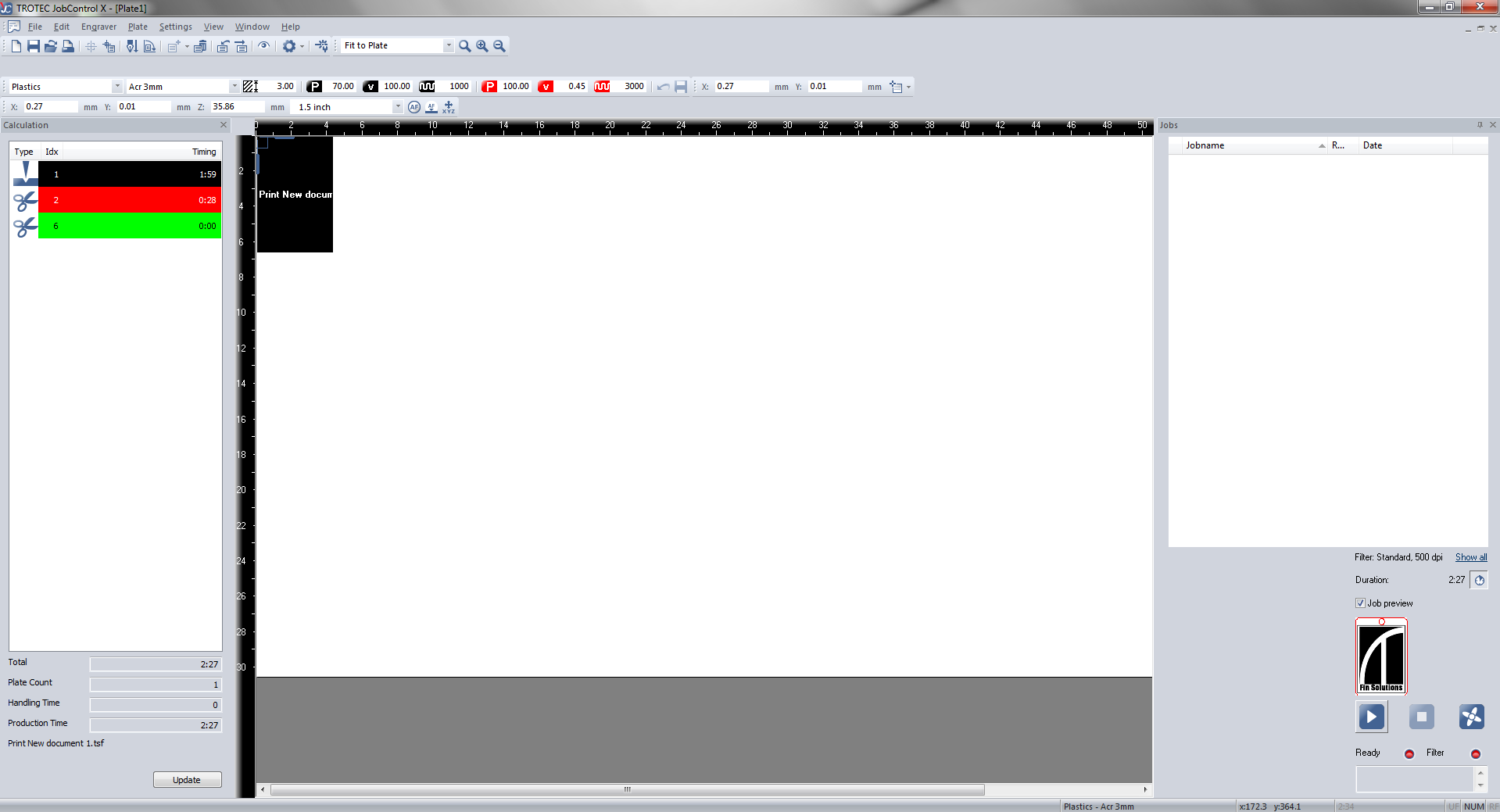
Add the job to the work place.
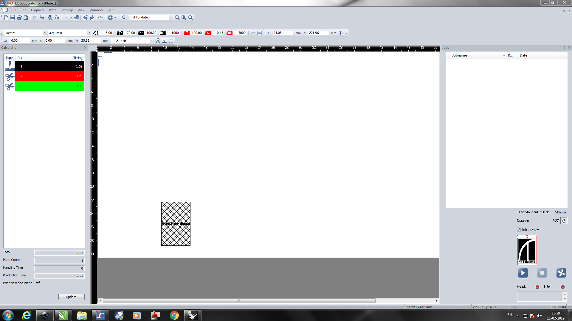
now postion the laser where to start cut and aline the job in the window like below and press ready..
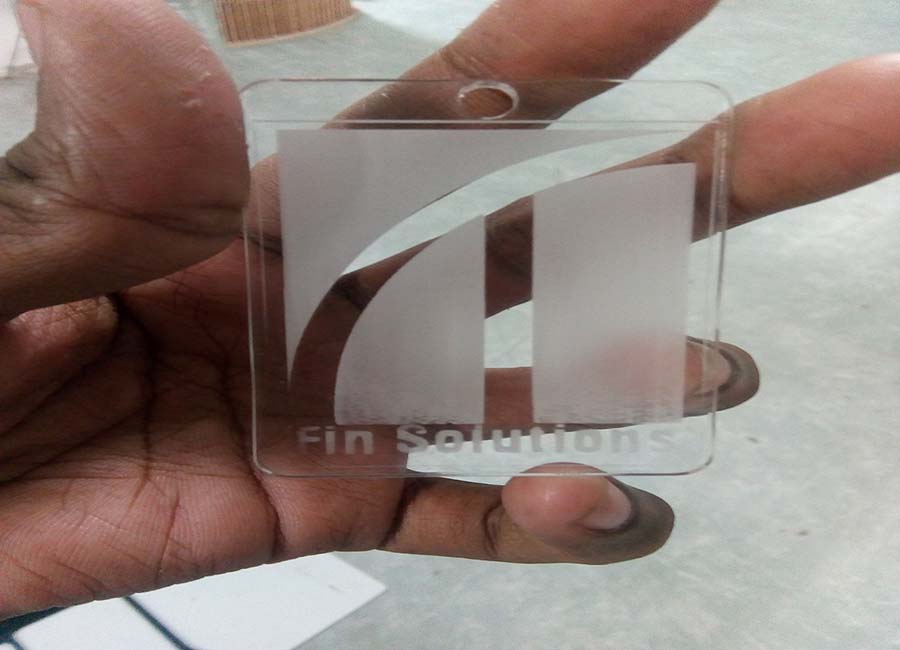
So I got the logo engraved and cut as a keychain.
Now we can start with parametric design...
Parametric Press-Fit design
The main assignment for this week was to create a parametric press fit design. Neil specifically asked us to make it parametric, because in parametric design each measurement is related to other values with some kind of equations. So that when we change one, the rest changes automatically. Parametric designing is a really good design principle to follow because it makes our project easily editable. In case of our press fit design, we can always use different materials ranging from cardboard pieces to acrylic and each of them has different thickness and kerf values. So redesigning every value for different materials is a difficult task. But in parametric design, all you have to do is to change the thickness value according to your materials and rest of the values automatically adjusts to this.
There are many software for parametric designing. I have used Autocad Fusion 360 for this task. My idea was to make a 2D drawing and extrude into 3D to see that the fit or assemble in the I want them to be...
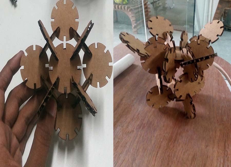
First I want to make something unique and different. But my instructor asked me to begin with something simple and easy to make. So I started to design a simple like a circle..
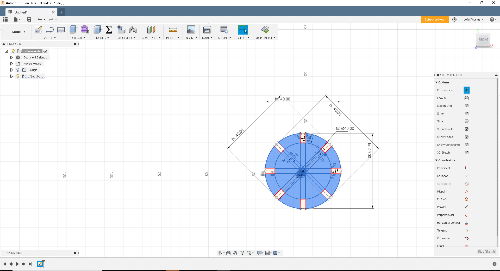
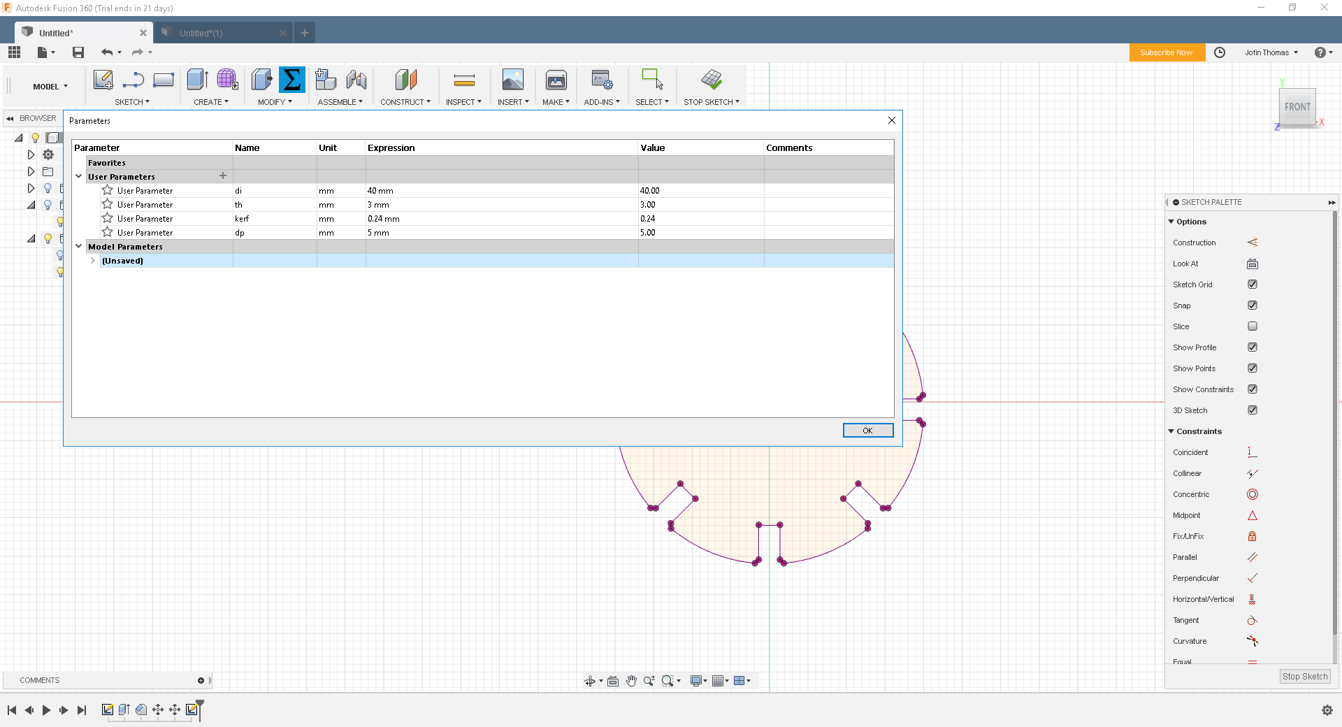
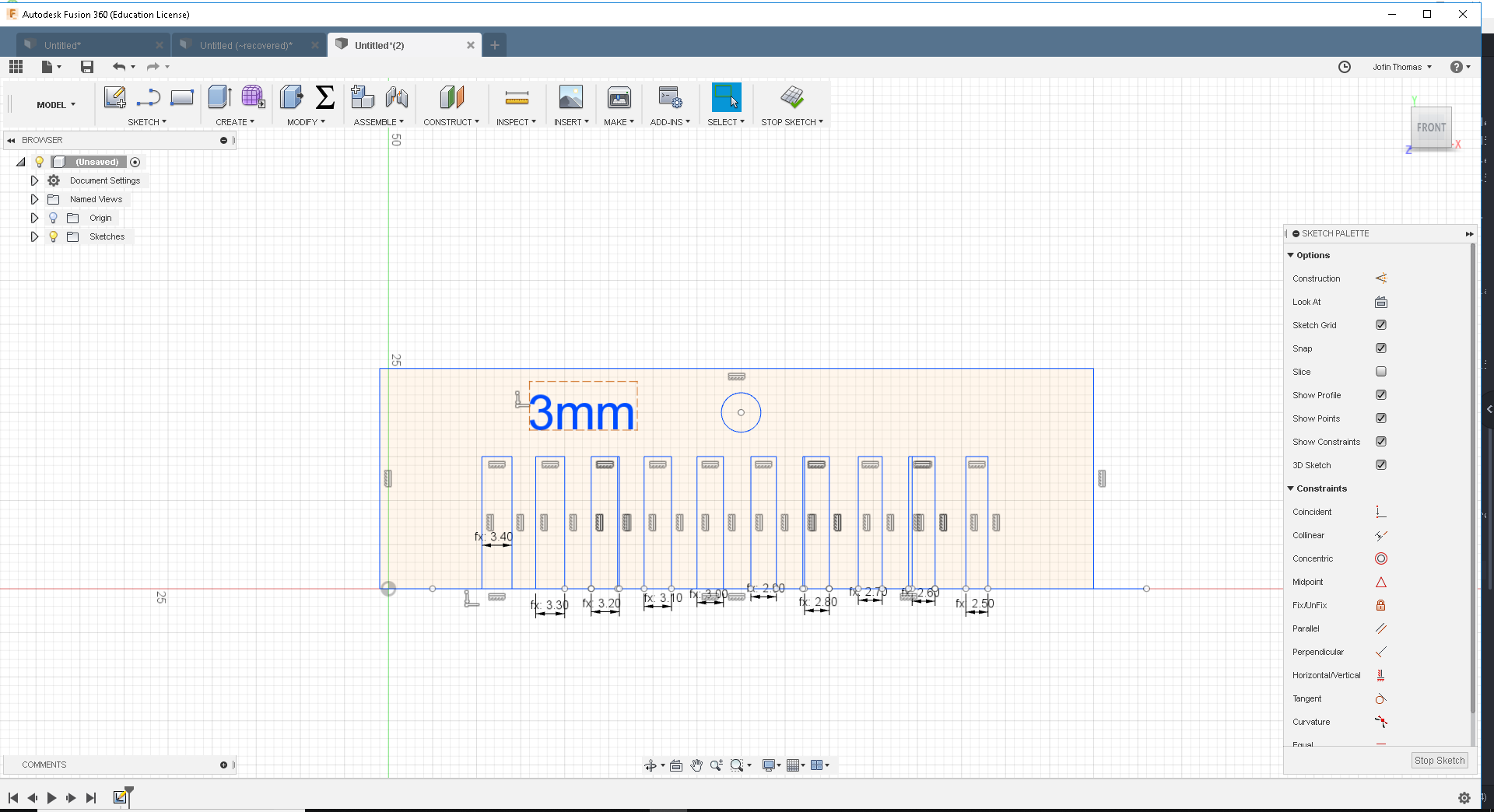
Fusion 360 have supported parametric design, so there is a tool for parametric design. I opened the spreadsheet with fusion 360 and add following values to it. The kerf value calculation was a bit tricky, plus I was not that good with maths, So this tool was very useful to me
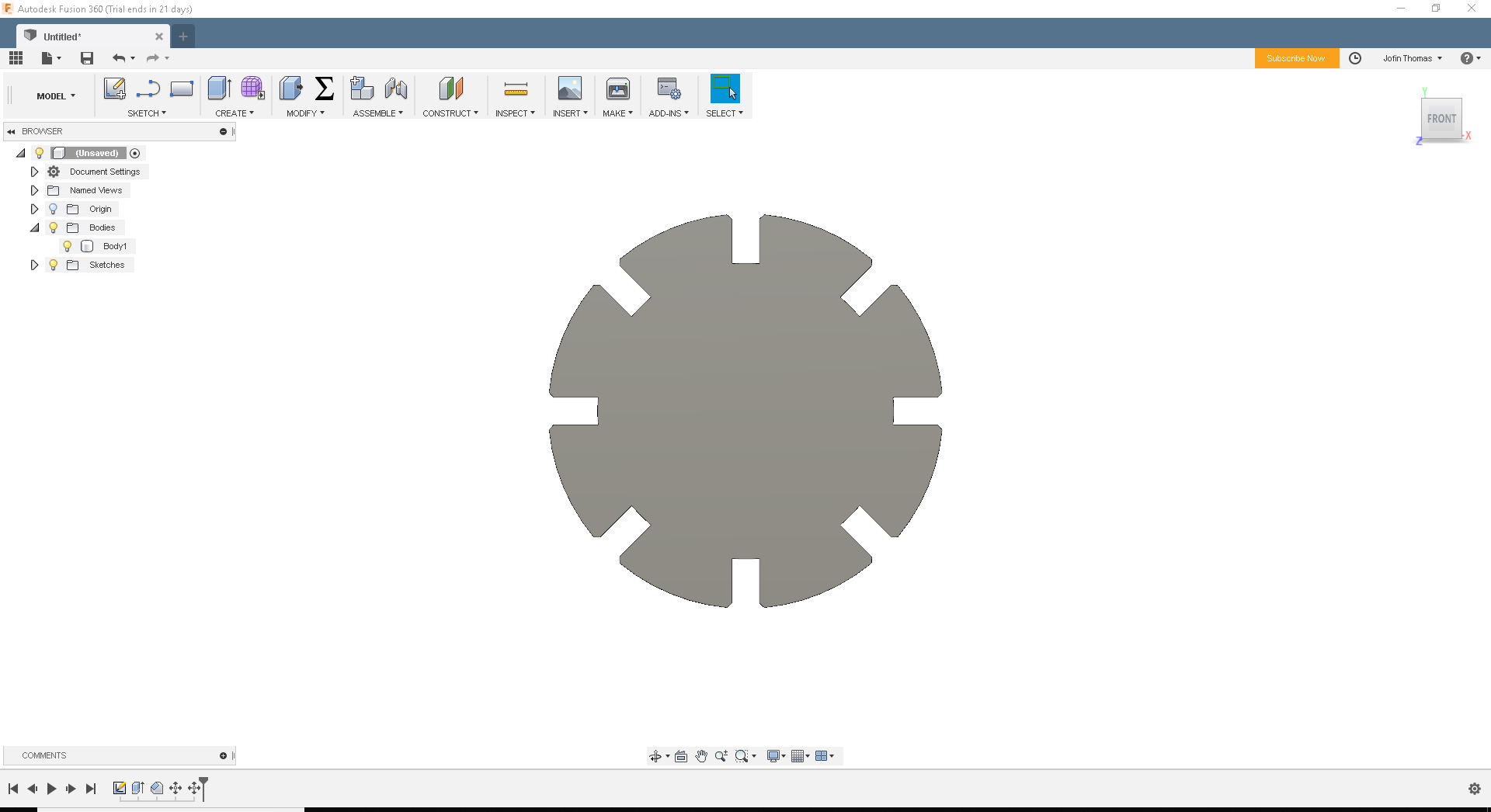
So I have done with sketching up the whole piece. Now to make them 3D and assemble. For that I use Extrude tool and made it a solid 3D piece.
The designing has done. So now it's time to cut the pieces from the cardboard using Laser cutter. So I exported as .dxf and put into laser cutter
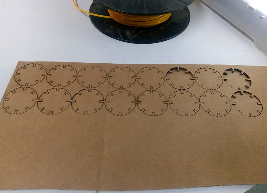
They look like this in real when they assembled...
You can download the files from Here.
Group Assignment
This week we got our first group assignment.
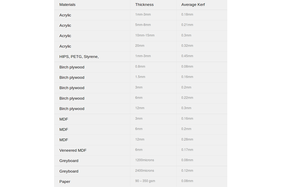
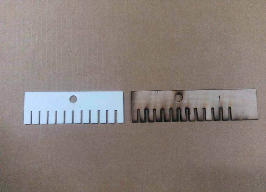
As part of testing out the laser cutter we had made a Kerf Scale. Kerf is simply the amount of materilal removed during the cutting process.The different kerf scales is as follows.
So we designed a scale and print it using laser cutter
Power - 75
Velocity - .90
Freq - 7000
Engraving Parameters
Power - 75
Velocity - 90
Freq - 500
So that's it for this. Let's discover more in the next week.....